
| Home | For sale | Site map | Contact information | Guest book | Leuchtpistole menu |
 Construction
of Die Leuchtpistole Construction
of Die Leuchtpistole |
|---|
|
Description of parts and functioning 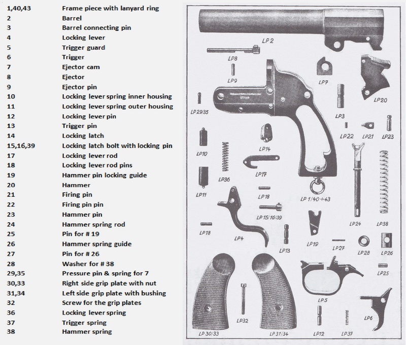 The starting point for this study is Fritz Walther's flare gun as it appeared when the patent was applied for in 1926. The flare gun was constructed with machined steel parts and all springs were of the coiled pressure spring type. The flare gun consists of two main parts; the barrel and the frame assembly. These parts can again be divided into the different mechanisms. The barrel consists of the barrel itself and the extractor mechanism. The frame contains the release mechanism and the trigger mechanism. 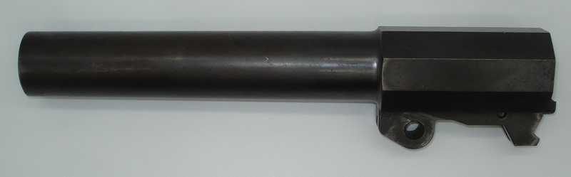 The length of the barrel was initially 230 mm long, and it was milled out of one piece of steel. It consists of the (traditional) tubular forward end, and the rear octagonal-shaped part that acted as reinforcement around the chamber. The barrel rail is situated below the octagonal part of the barrel. This part has been milled out of the same piece as the barrel and is made up of the combined seating for the barrel connecting pin and the ejector cam, the upper bearing for the locking lever spring housing, the barrel locking lug and the rest of the ejector mechanism. The barrel is smooth bored, with no instep between the chamber and barrel. In the rear end a step has been milled in to accept the rim of the flare cartridge. The ejector is located in a milled channel underneath the barrel, and is held in place by a cross pin. The ejector is free-floating and will be pushed rearwards by the ejector cam when the barrel is rotated around the barrel connecting pin. When the barrel is closed the ejector will be pushed back forwards by the rim of the cartridge that is inserted into the chamber, or by the rear edge of the ejector hitting the breach face if a cartridge has not been inserted. 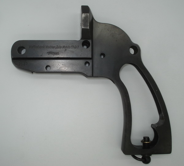 The frame piece is also milled out of one piece of steel and is U-shaped at the front to enclose the barrel rail when the barrel and frame piece are locked together. The frame piece has a transverse hole of 8 mm at the front for the barrel connecting pin which passes through the frame piece, the barrel rail and the ejector cam. The barrel is rotated around this pin when opening and closing. The barrel connection pin has a recessed groove in the middle that acts as a locking groove to prevent the pin from falling out. The locking of the barrel connecting pin is done by the ejector cam that is pressed upwards by a small spring-pressured bolt that sits in a hole in the frame. This pin is usually secured from falling out by a punch mark placed in the goods of the frame piece adjacent to the pin. The hole for the pin and spring is drilled all the way through. This allows access to the bottom of the pin from underneath, making it possible to remove it by a punch from below if needed. Behind the barrel connecting pin is the locking lever release spring consisting of three parts; the spring itself, enclosed by an upper (inner) and lower (outer) sleeve. The sleeves fit inside each other, and both have a pointy end. The large sleeve should sit in the bottom and it is not possible to lock the barrel to the frame piece if the spring sleeves are inserted upside down. The upper pointy end rests in the upper bearing for the locking lever spring housing, a bowl-shaped recess on the underside of the barrel rail. The lower pointy end presses against a corresponding recess located on the leading edge of the u-shaped locking lever which encloses the front of the trigger guard. Thus, the locking lever spring pushes the barrel upwards so that the barrel is rotated around the barrel connecting pin when the locking lever is pressed forward, and the ejector cam pushes the ejector backwards. The locking lever release spring presses on the leading edge of the locking lever, which is hinged on the locking lever pin, which is thereby pressed backwards to enclose the leading edge of the trigger guard. The locking lever, the locking lever rod and locking latch form a unit attached together by pins. By pushing the locking lever forward, the locking lever rod is pushed backwards, at the same time as the locking latch is rotated around the locking latch bolt and releases the barrel locking lug. The barrel will swing up at the rear end as a result of the pressure from the locking lever spring. The locking lever rod is shaped like a fishing hook and will act as a safety against untimely firing if the barrel is not completely closed, as it blocks the trigger's movement if it is not in the correct position. When the locking lever is released, the locking lever rod and locking latch will return back to their initial positions again by the pressure from the locking lever spring. By pushing the barrel up in front, the barrel locking lug will push the locking latch backwards until it snaps into the locking position when the barrel is completely pressed down at the rear. Thereby the barrel is locked to the frame piece again. The locking latch bolt is the only pin or bolt on the flare gun that is not locked by other parts. It looks like a screw, but is not threaded. The head contains a transverse spring-loaded locking pin that locks the bolt directly to the frame piece. 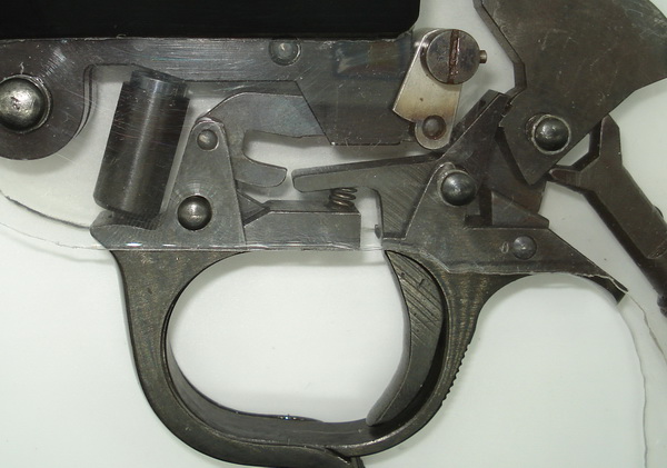 The breach face sits on top of the frame piece. When the barrel is closed the end of the inserted cartridge will rest against this. The breach face has a hole in the center for the firing pin. On the sides, the breach face has an octagonal shape that harmonizes with the chamber section of the barrel, but is slightly wider. The rear part of the frame piece consists of the grip strap. A ring for a lanyard is mounted at the bottom of the grip. This ring is mounted on a threaded stud which is screwed into the frame piece from below. It is secured against unscrewing by means of a disc and a cross pin. This causes the lanyard ring to rotate by screwing it in and out of the frame piece until it reaches the outer limits in both directions where it stops. This does not seem fully thought through and is thus an "exception" to an otherwise near perfect construction. This fault in the functionality is corrected later in the production, something that will be addressed later in the article "Evolution of the Leuchtpistole". The grip strap is covered by grip plates made of walnut, with a surface cut in the "fish skin" pattern ("Fischhaut"). The right plate has a recessed disc with a threaded hole and the left plate has a recessed disc that functions as a bearing for the grip plate screw. At the inside top the grip plates have a milled out lip which locks them to the frame piece. Above the grip plates, the frame piece has a transverse hole of 8 mm. This is used when the flare gun is mounted in the clamp of the mounting kit. We will return to this during the description of accessories. This hole was also later used for mounting the bubble-level sight and the shoulder rod when the flare gun was used as a weapon system. The grip conceals the hammer spring with the hammer spring rod and guide. The latter rests on a semi-circular shelf that is milled out on the inside of the grip. The other end of the hammer spring rod is fork-shaped and rests against the hammer. The hammer has two recesses on the underside for the two fork legs of the hammer spring rod with different lengths. The longest fork leg is at the back of the construction. The hammer has a wide, grooved surface at the top to give the thumb a comfortable and secure grip when it is cocked. It has a movable and replaceable firing pint which is attached with a cross pin. At the front edge, the hammer has two notches which act as a "resting notch" and "trigger notch". In the resting notch position, both fork legs of the hammer spring rod will lie against both recesses on the hammer, so that the firing pin rests hidden inside the frame piece. The resting notch will prevent the forward movement of the hammer unless the trigger is pulled. When cocking the hammer, the rear recess of the hammer will press against the rear leg of the hammer spring rod which in turn will compress the hammer spring. When the hammer is pulled far enough back, the trigger, which rotates around the trigger pin and is under pressure by the trigger spring, engages the trigger notch. When the trigger is pulled it will release the hammer which slams forward until it strikes against the rear side of the breach face, with the firing pin going through the hole in the breach face. During this movement the hammer spring rod flips over the center point, leaving the shorter front leg of the fork alone to compress the hammer spring. This presses the hammer back to the resting position. When the trigger is released, the resting notch on the hammer engages the trigger and prevents the hammer from being pushed forward without the trigger being pulled. 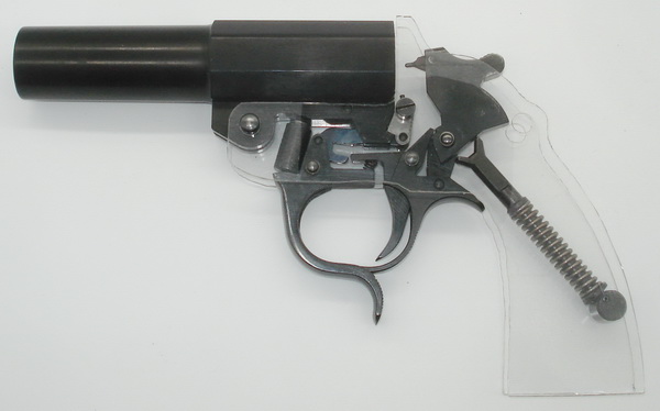 A plastic model that shows the internal parts and how they function. Behind the locking lever and around the trigger is the trigger guard, which is the most unique part on Walther's flare gun. This is machined out of steel with a slit at the top which gives it the abilities of a spring, in other words; it can be compressed slightly before it returns to its original shape. To make it easy to squeeze it together and give a good grip, it has a serrated portion on the rear. The trigger guard protects the trigger and prevents it from being operated without intention. In addition, it acts as a seat for the trigger spring and as a cover for the underside of the frame piece. But its most unique feature is that it locks the pins of the locking lever, trigger and hammer to the frame piece. This occurs by crescent-shaped recesses on the trigger guard engaging the grooves in the pins for the locking lever and trigger. At the back and top of the trigger guard is a movable guide attached with a cross pin. This locks the hammer pin. To summarize the mutual behavior of the parts in a concise way, the Dienstvorschrifte 409 (D/409) from 1935 describes the flare gun's functions as follows: How the parts of the flare gun lock work together.
|
| Home | For sale | Site map | Contact information | Guest book | Leuchtpistole menu |