The
MG Lafette was a pretty complicated piece of machinery for its time.
Some would say "typical German
over-engineering". It contains several systems that all work together.
The difference between the Lafette 34 and the Lafette 42 is mainly the
cradle. The weapon mounts and the trigger mechanism are simpler on the
MG42 cradle. In addition it has a different bolt box. Everything else
seems to be identical.
This page will only describe the Lafette 34. The change from
the
Lafette 34 to the Lafette 42 will be fully dealt with on the Wartime
development page. On
this page I will briefly explain the function of each of the
components that make up the Lafette. For an even better and deeper
understanding of the components you must visit my page Extreme details
or the pages about Evolution
of the Lafette (when they are finished).
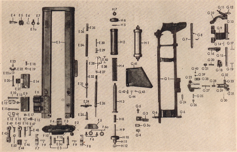
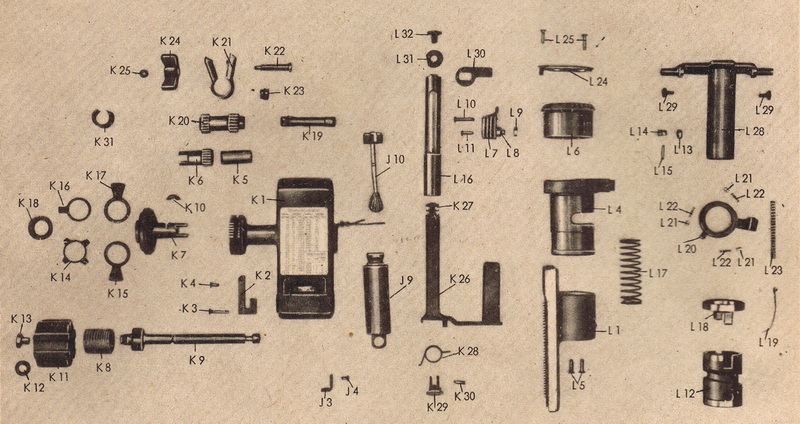
Main parts
| According
to the D 124/2 the Lafette 34 was made up of 5 main components: |
| - Unterlafette (Lower mount) |
| - Oberlafette (Upper mount) |
| - Richt- und Tiefenfeuereinrichtung
(Laying and searchfire mechanism) |
| - Lafettenaufsatzstück (Mount
AA
adapter) |
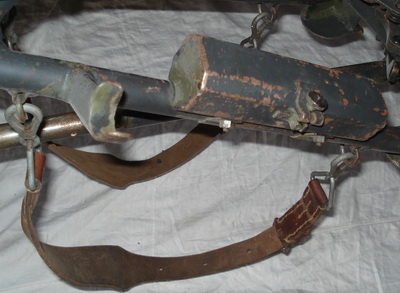
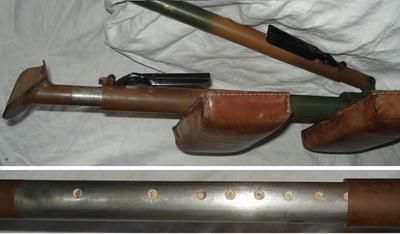
| - Trageriemen (Carrying slings) |
The last two components are today
generally viewed as
"accessories", so I will discuss them on the accessory page instead.
|
Unterlafette
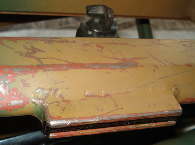
The lower mount consists of the mainframe,
the two rear legs, the front leg and the support strut. It is
made up of over 100 individual parts.
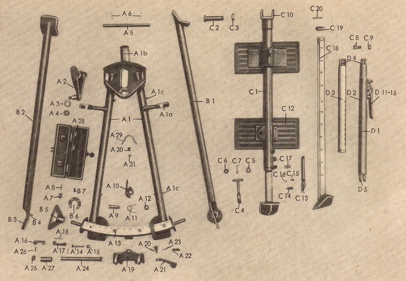
The
central part is the frame (A1), around which everything
happens.
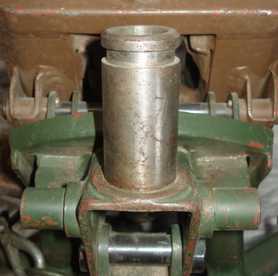
The upper mount is attached to the lower through the pivoting pin on
the turntable (A2). This part allows for both elevation and traction.
The rear legs are hinged at each rear corner and can be individually
adjusted in height through a large wing nut. Use of the legs is an
option, as the frame is equipped with a pair of paws that will do the
same job if the legs aren't needed. The angle of the front leg can be
adjusted to fit the terrain, and it can also be extended to acquire the
correct height. The support strut will adjust to the correct length and
ensure a firm connection between the front leg and the frame. At the
rear of the frame an arc (A13) is mounted that holds the slider (A19),
which is connected to the laying and search fire mechanism, and enables
the sideways movement of the upper mount. A box containing a spare
bolt is fastened to the left side of the frame.
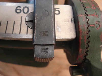 |
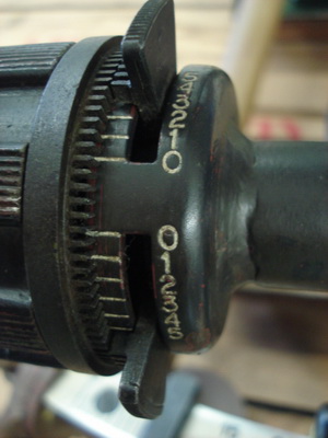
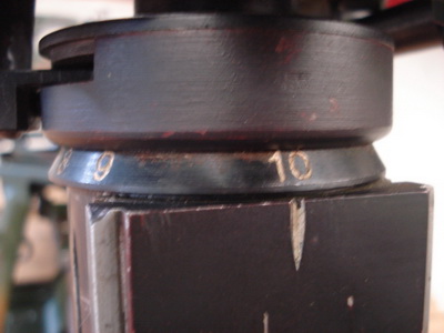
The arc
is divided into 650 mils. The system used by the germans was based
upon H/6400. A full circle would consist of 6400 mils (360 degrees)
and the arc would represent 650/6400 parts of a complete circle. There
is an adjustable stopper to each side of the slider. These will prevent
the machine gunner from firing at friendly troops when he is firing in
corridors between own forces. The alignment mark and numbers on the
legs enables the gunner to find the correct position for the legs.
|
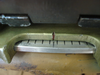 |
At
the center of the arc an alignment mark is placed at 32,5. A
corresponding mark is situated in the center of the slider and filled
in with paint. This enables the operator to zero the upper and lower
mount to each other (which comes in handy when you need to fold up the
mount). |
 |
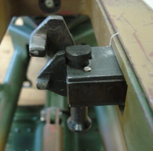
The front
of the slider has a locking lever that enables the operator to lock the
laying and search fire mechanism to
the arc in any given direction. |
 |
 |
The
front of the frame has the welded on pivot pin for the
Lafettenaufsatzstück and the two horns that was used to attach the
Lafette to a special bracket for transport on vehicles.
|
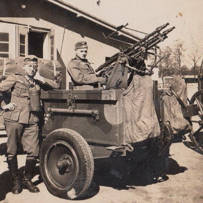
The
IF5 trailer with
the Zwillingssockel had two brackets at the back to mount the Lafette
34. A permanently attached canvas cover kept most of the dust out
during transport. |
 |
The
removable bolt box is mounted on the left side of the frame. According
to the manual it could, under
special circumstances, be repositioned to the
right side of the
frame or on the left rear leg. Note also the
D-rings for the carrying straps and the support cradle for the folded
leg, welded to the
frame. |
 |
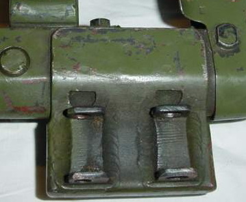
The
front leg and the support strut has the same locking mechanism, and
both have milled out dots that have been filled in with paint to aid in
the set up process. The leg has two support pads that rest against the
carriers back. The upper one is non-adjustable, while the lower one can
be loosened and slid up or down. |
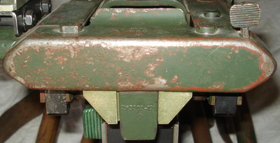
Oberlafette
The upper mount consists of the cradle,
the weapon mounts and the spring assembly. It is made up of over 140
individual parts.
The cradle (E1) is attached to the lower mount
through the turntable (A2 above) in front, and to the laying
and search fire mechanism through two spring pressured arms (E43) that
helps lock the mechanism to the cradle. It holds the recoiling frame
(G1) with the weapon mounts and the buffer
spring assembly
(H1). The optic sight's mount sits on a bracket that is welded to the
rear left side. The mechanism to fire the weapon from the remote
trigger runs on the inside to the right. The buffer assembly is
anchored to the cradle at the front, while the rear is attached to the
center crossbar of the frame with the weapon mounts. The frame with the
weapon mounts rides on the 4 rollers (E5)
that is mounted inside the cradle from above with the four pins (E4).
The
trigger mechanism, the spent casing tray and the weapon
mounts rides on the frame
with the weapon mounts.
|
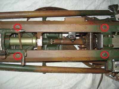
The four
pins that holds the rollers guiding and carrying the recoiling frame
with the weapon mounts are
easily seen from above. |
 |
The bracket
for the optic sight's mount is welded
to the
rear left side. |
 |
The trigger mechanism sits in the
inside right wall of the frame
with the weapon mounts.
It is adjustable for
automatic/semi-automatic fire by pushing down the serrated button on
top or pushing it back up again. The pin at the bottom is also used to
pull the trigger to the front when the weapon is mounted to the cradle.
|
 |
The
trigger housing sits opposite
the trigger mechanism. This is not an adapter or a mount, it simply
contains the leverage that
controls the trigger mechanism on the opposite side. Note the two small
pins holding parts of the mechanism |
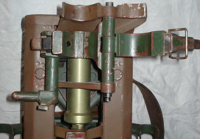 |
The recoil spring assembly is
contained inside the tube that is anchored to the cradle in front and
attached to the recoiling frame
with the weapon mounts at
its rear.
The forward gun mount with its break-down mechanism can also be seen in
this picture.
The MG34 barrel shroud is clamped down with a standard box lock. But
locking the clamp will at the same time move the axel rod (G7) to the
rear until it enters a hole at the rear of the barrel shroud on the
actual weapon. When twisting the arm on the left upwards the
forward gun mount with the barrel shroud will hinge to the right
pivoting around the axel rod (G7), allowing access for a barrel
change. |
 |
There is an arm mounted
underneath the cradle on the left side. This will hit the Searchfire
mechanism
every
time the cradle recoils. |
 |
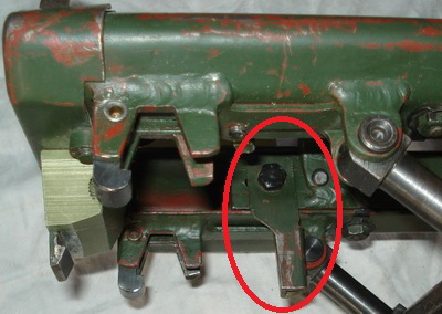
The rear cover contains the locking
mechanism that will keep the Lafette either in the open or closed
position. On later models the release button was moved to the
underside as it was prone to break when the Lafette was transported.
|
 |
Pushing
the square button on top right will release the locking catch
in the center bottom when the Lafette is collapsed. Pushing it when the
Lafette is in the raised position will release the two arms that join
the Laying and search fire mechanism and the upper mount. The top can
now be raised and the mechanism swung forwards to allow the upper
cradle to fold down. |
Richt-
und Tiefenfeuereinrichtung
The Laying and search fire mechanism consists of (no
surprise!) the Laying
mechanism and the Search fire mechanism. It
is made up of over 70
individual parts.
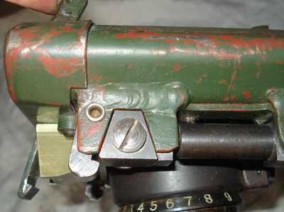
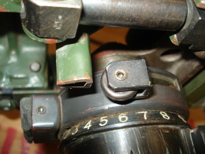
The height adjustment wheel (K11) enables the gunner to change the
elevation of the gun, and it can be limited by the stoppers (K17 and
K15) to shoot over the heads of own troops. The wing nut (K24) adds
friction to the elevation adjustment for better accuracy. The tube (J9)
acts as a handle for sideways movement and contains oil and a brush
that can be used during maintenance. To my surprise, it is specifically not used
to ensure that the slider (A19) runs smoothly along
the arc (A13). The tube also acts as the counterbalance for the
trigger (K26). The search fire mechanism is set by the slider
(L7) and operated automatically by the arm (G3 above) hitting the lever
(L20). The leverage for the trigger runs inside the search fire and
connects with the trigger mechanism in the cradle on top of
the search fire.
|
By pressing the elevation adjustment
wheel to the right its teeth will engage with those on the stoppers,
preventing the MG from shooting outside of approved elevations
(in order to protect own troops). |
 |
The button on the opposite side of the
mechanism aids in unlocking the elevation adjustment wheel when it is
pulled out to the left. |
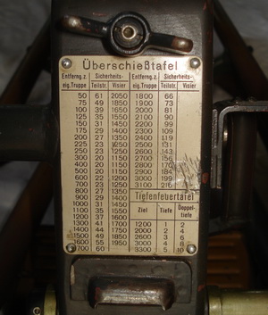 |
The rear of the laying mechanism holds
the wing nut that locks the elevation adjustment, the Überschieß-
und Tiefenfeuertafel and the lip that keeps the Lafette folded up. |
 |
The rear side of the search fire
mechanism has an alignment mark that enables the operator to see which
setting the
mechanism is on. |
 |
The recoiling actuator arm on the
cradle hits the lever of the search fire mechanism for every shot, and
elevates or depresses the MG according to the setting. The rubber pad
to
the front rests against the support strut when the Lafette is folded up
and acts merely as a shock absorber during transport. |
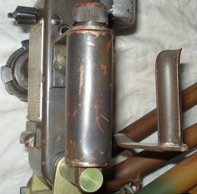 |
The oil tube contains a small amount
of oil, with a brush in
the top cap to enable application. At the same time it acts as a handle
for
sideways movement and a counterbalance for the trigger handle. |
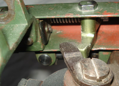 |
Pressure on the trigger handle
is transferred on top of the
search fire to the trigger mechanism in the
right
side of the cradle. The
green aluminum arm pivots on the bolt and pushes the spring pressured
arm forwards to engage the trigger mechanism on the right side of the
cradle. |
That was the quick guide to
the Lafette
and most of
its functions. For an even better understanding of the individual
components I will have to take the sucker apart and show you how it is
all connected and works. The Lafette
in extreme
details will give you this insight. For details about the
evolution of
the individual parts you will need to see the Evolution
of the Lafette 34 and Evolution
of the Lafette 42.
|


 Construction
and details of the Lafette
Construction
and details of the Lafette